Ocean current electricity – clean energy source Eng. Doan Manh Dung (Dec-2021)
Kinetic resources from ocean currents
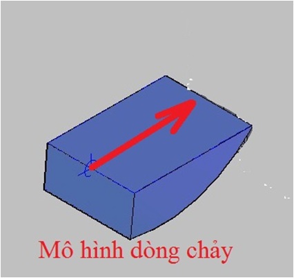
Humans are worried about global warming due to the use of fossil energy sources. The use of hydroelectricity provides a clean energy source, but the process of making reservoirs has a lot of impact on the environment and causes danger during big storms and floods. Many renewable energy sources have been born, including solar power and wind power which are developing rapidly in Vietnam. However, people worry that the manufacture of photocells also has a lot of impact on the environment. Wind power is still very expensive. There is another Resource in the world that can provide clean electricity which is the natural flow of rivers, seas, tides, tail currents of hydroelectric plants. Natural flow is characterized by depth, width, direction, and speed. The surface flow rate is highest and decreases gradually when reaching the bottom. The steady flow direction is very suitable for industrial mining. Water and wind energy sources are calculated by the formula: E= 0.5 mvv. Because the density of sea water is 830 times that of air, sea curent provide an extremely large source of energy beyond human imagination.
Dynamic resources of ocean currents in Vietnam Due to the difference in temperature between the Equator and the North Pole in 365 days/year, there is a bottom ocean current from the North Pole to the Equator in 365 days/year. Since the earth rotates from west to east, the bottom ocean currents move from east to west. Thanks to the West Pacific coast gradually drifting to the west when moving from the North Pole to the Equator, therefore the bottom layer currents close to the central coast of Vietnam from Hon La – Quang Binh to Cape Ke Ga – Binh Thuan with a length of 1000km, at the mouth of Gianh river with a width of up to 20 km, near the shore, shallow water, stable folow direction with North-South, the highest speed on the west coast of the Pacific Ocean. In winter, the northeast wind for 8 months creates a surface current running in the north-south direction. The combination of bottom and surface currents has formed extremely strong ocean currents on the central coast of Vietnam. USA and Dai Loan have officially reported on the dynamic resources of ocean currents in central Vietnam by satellite data. There are 12 locations with high flow rates on the western coast of the Pacific Ocean. In Central Vietnam, 7 locations have the highest flow rates, followed by Japan, Taiwan, and the Philippines. Seven locations in central Vietnam have the highest flow rate of 1.26 m/s, average 1.18 m/s, and lowest 1.05 m/s.
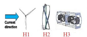
Update technology of exploiting ocean currents The world today is exploiting the kinetic energy of ocean currents or tides, rivers by turbines with propellers rotating in the water. All propellers modes have weight and can only get energy moving through the operating locus of the propeller. Moreover, the generators are located in the water.
Both of the above factors make the power low and the generator cost high, making it difficult for marine electricity to compete and put into practice.
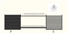
Figure 1: Types of propeller that the world is using today.
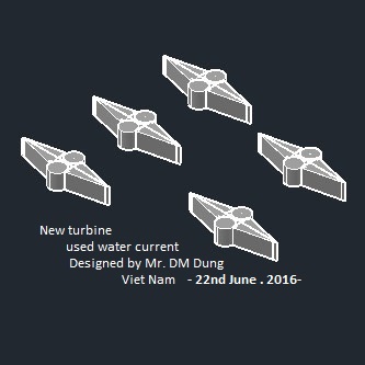
New technology of Vietnam Vietnam’s solution is to use turbines in the form of “Rotary Drums”. It is a cylindrical propeller located in the water, with a cover frame outside. The inside of the cylinder has a empty place so that the Archimedes force pushes the drum to float in the water. Half of the drum body is covered. The drum wall has a tooth to receive the force from the flow. The method of receiving energy here is not force but torque. Thus the turbine will rotate when there is even the smallest flow. The power generation system is located on the water surface. Thus one module can place 2 rotating drums as shown and can take full power with depth. With the 2 staggered rows arrangement, the modules can take all the energy flowing horizontally. This is the optimal solution to receive the full kinetic energy of the natural flow.
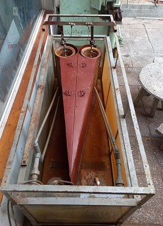
Figure 2: Rotating drum and frame
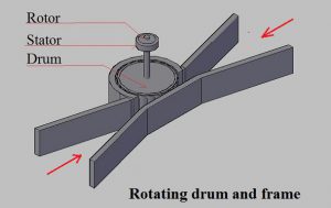
Figure 2-a: Rotating drum for calculation
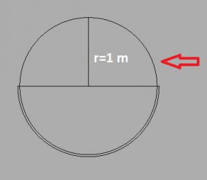
The generator is a prefabricated concrete block in a floating or submerged dock and pulled to sink at the place operating and it has a lifespan of up to 30 years. Concrete blocks when not in use can be raised and put in a certain position to serve as a breeding ground for aquatic animals. Rotary drum systems are as light as possible, requiring less material and being recyclable.One way current called as DC. Two way current called as AC.Rotary drums are specified with standard dimensions to facilitate fabrication and transportation. The rotating drum has a radius r = 1 m and a depth of 2 m. For simplicity in calculation, here will not calculate the flow energy acting on the frame and then acting on the rotating drum and assume v = 1m/s.
E= 0.5 mvv
The area of cress-section receiving the energy is 2 m2.
Mass of water acting on the drum:
M = 0.5 x 2 m2 x 1m/s x 1m/s = 2 m3 = 2000 kg.
1 kg = 9.8 N.
The source of energy from the kinetic energy of the water move on the rotating drum:
E= 0.5 x 2000 x 9.8 N x 1m/s x 1m/s = 9800 J/s = 9800 W.
Estimated conversion capacity is 70%, so the generating capacity is 7000 W = 7 KW.
Since the “Module” has 2 drums, the generating capacity will be:
P2m = 2 x 7 KW= 14 KW
Using the depth of 10 m, the generating capacity will be:
P10m = 14 KW x 10m/2 = 70 KW
Integrated in a large module with 7 pairs of drums, we will have a capacity :
7 x70 KW= 490 KW
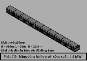
Integrating 10 large modules together will have a capacity :
490 KW x 10 = 4900KW= 4,9 MW
Figure 3: “Module I-AC” consisting of 2 rotary drums.
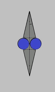
Figure 4: Mechanical model for “Module I-AC”
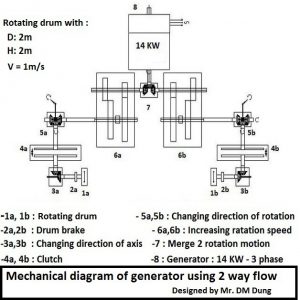
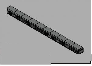
Figure 5: “Module II-AC” includes 7 “Modules I-AC”.
B= 39.4m, L= 33m, H=22.4 m

Floor 1: Base floor
Floor 2: Floor for sand moving
Floor 3: Floor receiving energy
Floor 4: Floor for tide moving
Floor 5: Floor for operating
Figure 8: Layout of 7 pairs of rotating drums viewed from above.
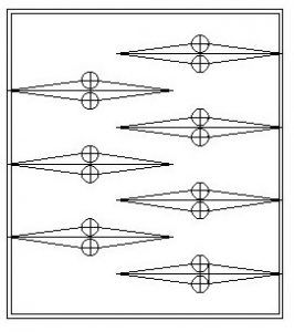
Figure 9: The cube of layout of 7 pairs of rotating drums.
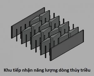
Figure 10 : Combination of 10 “Modules II-AC”
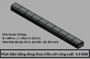
B= 394m, L=33m, H= 22.4 m
Figure 11: “Module I-DC” consisting of 2 rotating drums.
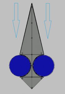
Figure 12 : Mechanical model for “Module I-DC ”.
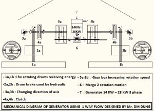
Figure 13: “Module II-DC” includes 7 “Modules I-DC”.
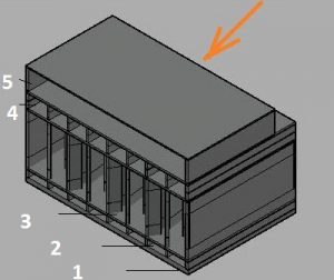
Floor 1: Base floor.
Floor 2: Floor for sand moving.
Floor 3: Floor receiving energy.
Floor 4: Floor for tide moving.
Floor 5: Floor for operating
Overview of concrete blocks placed on the seabed. This model corresponds to a mining depth of 10 m. Depending on the specific location to change the base layer, sand layer elapsed, mining layer, tidal floor up – down.
Figure 14: Layout of 7 pairs of rotary drums, viewed from above.
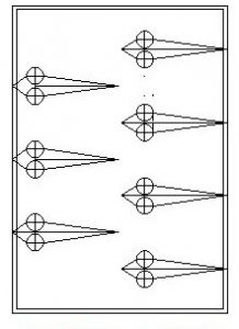
Figure 15: The cube of layout of Ar 7 pairs of rotating drums.
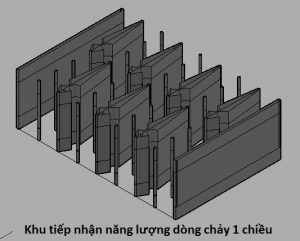
Figure 16 : Connecting 10 “Modules II-DC”.
B= 394m, L = 26m , H = 22.4m
Development strategy of Sea current electricity in Vietnam Because the power supply is very large, the strategy of both hydrogen electrolysis and connection to the grid is chosen. Install a few more concrete modules to form a berth for receiving empty tanks and supply hydrogen-filled tanks to the carrier. This way can helps the investor being proactive. Liquid hydrogen is a clean source of future materials that can be used for thermal power plants, chemical industry, civil engineering, and transportation./.